On this page we will create the design for the main entrance door of the Amerigo Vespucci, one of the most beautiful tall ships in the world. We will export production templates for milling or photo etching.
The model file is called Amerigo Vespucci - EntranceDoor and is installed with the samples. The scale is 1:84.
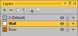
Layer
In addition to the door itself, we will also create the surrounding wall. For better visual separation, we organize both elements in separate layers. So first we go to the Layer Editor, create two new layers, rename them to Wall and Door, and set a different color for both. We start with the wall and activate this layer with a double click. New bodies are created in this layer.
Our created layers
Creating the Wall
We construct the wall using a Box. To make it easier, we activate the snapping for the grid via the context menu (right mouse button) of the viewport or the Edit tab of the ribbon menu. Both switches - Enable Snapping and Grid - must be activated for this. We set the grid to a Stepping of 1.0 mm.
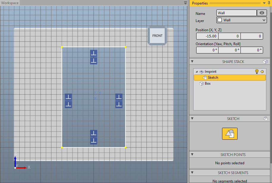
We select the Create Box tool on the Model tab and first select the two points of the base at -15.0, 0.0 and 15.0, 2.0 on the working plane, resulting in a length of 30.0 mm and a width of 2.0 mm. We then enter the height of 25.0 mm via keyboard and confirm the entry with the Enter key. Our box should now be in place. If values have to be corrected again afterwards, this can be done in the property pane. We change at least the name for this new body.
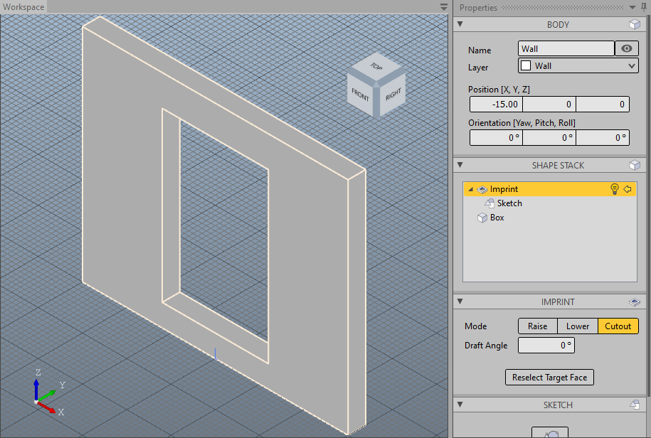
Now we define the door cutout. To do this, we use the Imprint modifier. We choose the tool Create Imprint in the mode Cutout. To do this we click on the arrow in the button in the ribbon menu and select Cut-Out a Face from the menu that then opens. We select the front surface of our wall and automatically switch to the sketch editor. We draw a rectangle from -9.0, -6.0 to 10.0, 6.0. Then we close the sketch editor with the Esc key or one of the buttons reading Close Editor.
We now have our wall with a door cutout.
Wall in the sketch editorThe finished wall
Creating the Door Frame
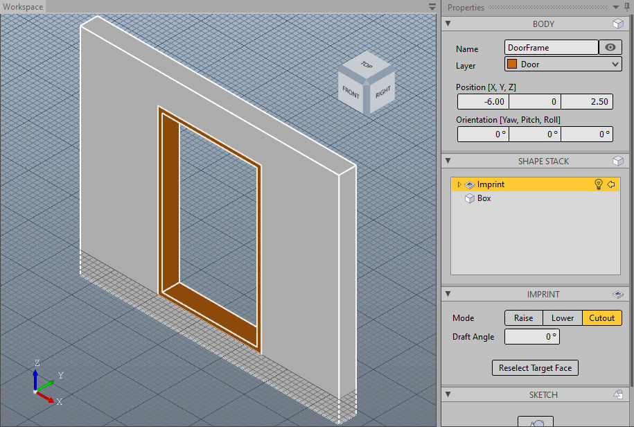
For the door we switch to the Door layer, e.g. by double-clicking on the layer in the layer editor or by selecting the layer in the dropdown box in the ribbon menu. Then we put the working plane at the height of the door cutout. For this we select the tool Align Working Plane in the Edit tab. This function is also available in the toolbar of the context menu of the viewport. We use the front left vertex as the target of the alignment.
First we create the door frame. We proceed in the same way as with the wall: we create a Box that is flush with the wall and then create a cut-out with the Imprint modifier from -9.0, -5.5 to 9.0, 5.5. The stepping of the grid should be set to 0.5 mm.
Tip
The snapping function can make work extremely easy, especially if reference points, edges or surfaces are available. In this case, when creating the box for the door frame, the vertices of the wall can serve as a reference for all points to be selected.
The door frame is ready
Creating the Door
The door has two symmetrical door leaves, so we will simplify the work by constructing only the left door leaf and deriving the right one from it. We first align the working plane to the door frame. Since the door is lower, this time we take the rear left vertex as a reference and open a box from there so that it fills half of the door frame in width and in depth.
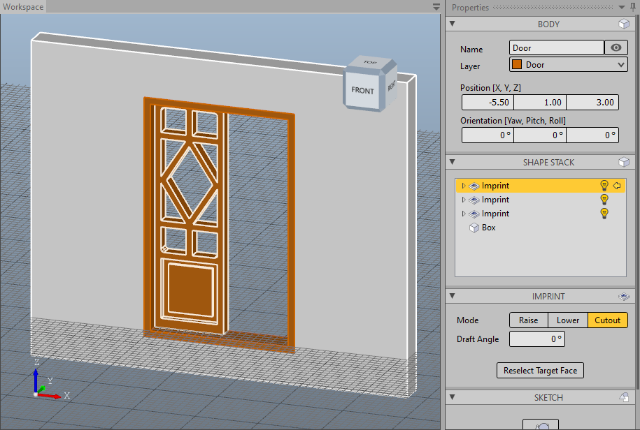
We create the decoration in the lower part of the door using two Imprints, but this time we use the lower mode once to achieve a recess of 0.5 mm, then the raise mode to create an increase of 0.3 mm within this recess.
We create the decoration in the upper part with a single Imprint in cut-out mode. A little work is required in the sketch editor to recreate the cutouts nicely.
The upper decorations
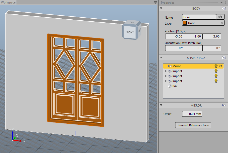
For the second door we add a Multiply Mirror. To do this, we select the Mirror menu item in the Edit tab and select the middle side surface of the door leaf as the mirror surface.
The finished door
Templates for Milling
Since we want to make the door in one piece, we add the door frame to the door. For this we select the menu item Fuse in the tab Model and select the door frame.
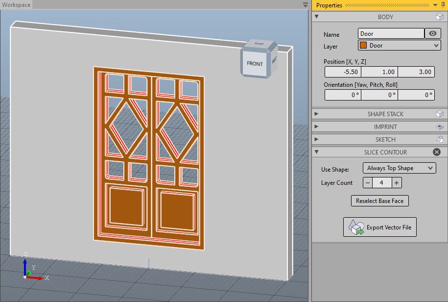
In order to mill out the door, we need the contour lines of all edges so that we can create milling paths from them in the CAM tool. These are created by slicing the construction layer by layer and exporting the resulting cutting lines as vectors. To do this, we select the Slice Contour menu item in the Toolbox tab. This tool shows us the cutting lines through the body in red; we get the reconstruction as the shape of the body, as if we were to completely mill through the material with the resulting contour lines. We increase the layer count in order to use more slicing planes, and find that with four layers the decorations also have good contour lines. By clicking on Export Vector File, we save the vector drawing for further processing.
Preview of Slice ContourThe exported vectors
Templates for Photo Etching
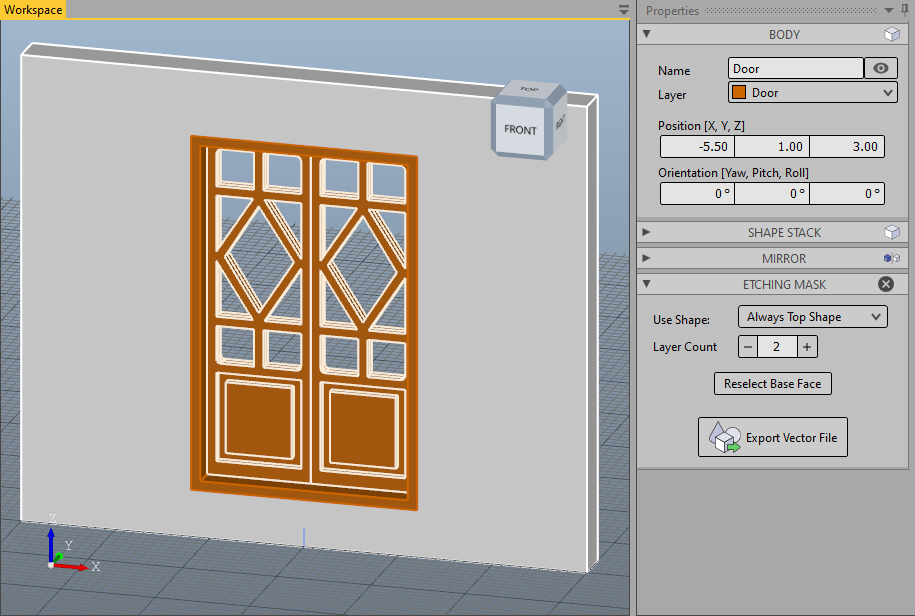
For the production using photo etching, a film mask is created with which the material to be etched is exposed on both sides. We are therefore always limited to two layers. As with the creation of contour lines, the construction is sliced in layers and this time the resulting cut surfaces are exported as a vector drawing. To do this, we select the Etching Mask menu item in the Toolbox tab. This tool shows us as a shape the reconstruction of how the part would look after etching. By clicking on Export Vector File, we save the vector drawing for further processing.
Preview of Etching MaskThe exported mask
The Result
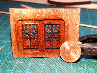
We have now created templates for creating the part using milling or photo etching. Which of the two production methods is more suitable depends on many factors.
Here is an example of the subsequent production with the milling machine.