What's new in Release 3
This page lists all new features and changes of the version 3.0 compared to the previous version.
Live Tools
The biggest expansion is the introduction of Live Tools. These are interactive tools for setting the parameters of the currently selected shape. The tools are displayed in the viewport and can be operated there directly; the results are usually immediately visible. This allows parameter settings to be aligned with the model much more intuitively and adjusted more quickly.
The live tools are provided by almost every shape and modifier that can meaningfully map parameters in the viewport.
Modelling
New Modifier
Offset makes a sketch or solid thicker or thinner by creating parallel copies of each curve or face at a specified distance and closing the resulting gaps.
Cross Section creates a sketch by cutting the solid with a plane.
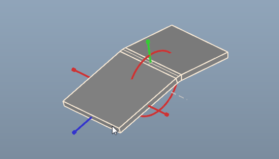
Halved Joint is for the connection between two solids. It builds a junction by removing half of the thickness from each part.
Scale to modify the size of a sketch, solid or mesh uniformly or non-uniformly.
New Features
Mirror gets three new options:
Keep Original can be deselected to discard the original shape.
Merge Faces create contiguous surfaces from the mirrored and the original face.
Also one of the standard planes can now be selected as the mirror plane.
Revolve: When creating the modifier, the rotation axis can now be selected interactively in the viewport.
Linear Array and Circular Array: When creating the modifier, the level on which the copies are distributed can be selected interactively in the viewport.
Shape Stack Converter: There are two new tools available to collapse the shape stack and replace it with a solid or a sketch containing the result of the former shape stack.
Boolean Fuse: New option Merge Faces to merge contiguous faces.
Extrude: New option Merge Faces to merge contiguous faces.
Slice Contour: The slice layer positions can now be freely defined as an option.
Workflow
The Transform tool has been given a new look and feel to harmonize it with the new live tools and to improve usability.
The tool for translating points and segments has been adapted to the new style and has been given an additional rotation function.
The Create Sketch tool offers the three standard plans for selection in the center of the working plane.
View settings of the sketch editor are retained even after transformation of the sketch.
Fillet and Chamfer have been given new tooling:
The selection and deselection of edges has been simplified so that selected edges are no longer hidden.
The radius or distance can also be set visually in the tool.
Slice Contour: New option to display the reconstruction or the original shape.
The tool for creating has been given an option to round the sizes according to grid size.
During creation, the preview shapes are already displayed in the visualization of the active layer.
The currently selected plane is displayed as a preview.
Vertices and edges determine the location of the plane, but do not change its orientation. This allows the alignment to be defined precisely by first moving to the associated face whose alignment is to be used as orientation and then to the vertex or edge to move the plane to this location.
Edges and vertices of sketches can also be selected. The resulting plane is coplanar to the sketch plane.
Grid
In the bottom right-hand corner of the viewport you will now find the current grid stepping together with a scale ruler. Scrolling with the mouse wheel on this display changes the grid stepping for quick adjustment.
The zero line in the X and Y directions are marked as a red and green line respectively for better orientation.
Layers can be sorted in the layer editor using drag'n'drop.
Workspace
The selection behavior has been adjusted to match the windows standard: LMB selects exclusively, Shift + LMB extends the selection, Ctrl + LMB toggles the selection. Mouse movement with the left mouse button pressed starts the rubberband selection.
Rotation now always takes place around the center of gravity. This is determined at the start of the rotation and remains in place until the individual rotation process is completed.
The shortcut E is used to start editing a shape if a corresponding tool is available (e.g. Sketch, Fillet, Chamfer).
Document Explorer
At the top of the document explorer there is an input field for searching the list of all entities by name.
On the right-hand side of this line there is also a button which provides a menu for setting filters and sorting.
Exchange
The Create Drawing From View dialogue now offers the option of transferring only the selected entities to the drawing.
Scripting
The version of the CAD kernel OCCT was increased to 7.8.0. This results in some changes which can be looked up on the OpenCASCADE website.
There are the following changes in the mapping of OCCT classes:
Most collections can be iterated as usual in C# via foreach, LINQ extensions are available.
The method GetType(), already reserved in C#, has been renamed to GetGeomType() in earlier versions. This has been changed to GetCurveType() or GetSurfaceType() depending on the return type.
The names of enum members have been shortened by the repetition of the enum name for better readability.
The class structure of tools and actions has changed slightly. Adjustments may be necessary here. The new usage method is shown in the scripting tutorial.